HOME

ET Solution Center index

HOME

Triangulated Irregular Network


The TIN model represents a surface as a set of contiguous, non-overlapping triangles. Within each triangle the surface is represented by a plane. The triangles are made from a set of points called mass points.

Mass points can occur at any location, the more carefully selected, the more accurate the model of the surface. Well-placed mass points occur where there is a major change in the shape of the surface, for example, at the peak of a mountain, the floor of a valley, or at the edge (top and bottom) of cliffs.

The TIN model is attractive because of its simplicity and economy and is a significant alternative to the regular raster of the GRID model.

Quick comparison:

  TIN GRID
Advantages
  • ability to describe the surface at different level of resolution
  • efficiency in storing data
  • easy to store and manipulate
  • easy integration with raster databases
  • smoother, more natural appearance of derived terrain features
Disadvantages
  • in many cases require visual inspection and manual control of the network
  • inability to use various grid sizes to reflect areas of different complexity of relief.
 

The Delaunay Triangulation

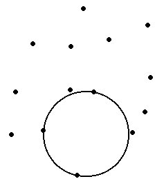
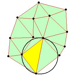
Delaunay triangulation is a proximal method that satisfies the requirement that a circle drawn through the three nodes of a triangle will contain no other node

4032001TIN00.jpg (5819 bytes)                     4032001TIN01.jpg (16187 bytes)

Delaunay triangulation has several advantages over other triangulation methods:

  • The triangles are as equi-angular as possible, thus reducing potential numerical precision problems created by long skinny triangles
  • Ensures that any point on the surface is as close as possible to a node
  • The triangulation is independent of the order the points are processed
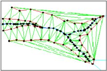
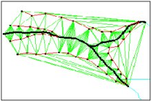
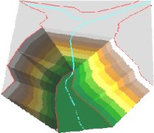
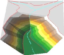
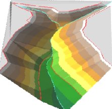
TINs from contours

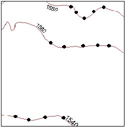
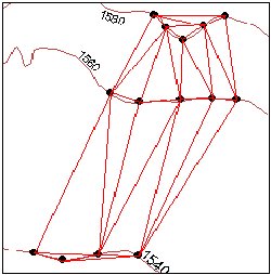
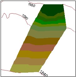
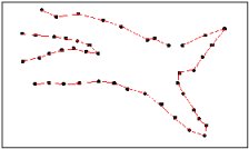
Contours are a common source of digital elevation data. In general all the vertices of the contour lines are used as mass points for triangulation. In many cases this will cause the presence of flat triangles in the surface.

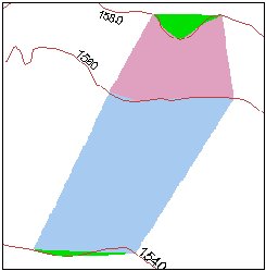
Flat triangles are created whenever a triangle is formed from three nodes with the same elevation value

Flat triangles are frequently generated along contours when the sample points occur along the contour at a distance that is less than the distance between contours. When these "excess" vertices are not removed , the Delaunay triangulation discovers that the closest sample points are those along the same contour, causing the generation of flat triangles.

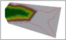
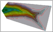
The flat triangles have a slope of 0 and do not have defined aspect. They might cause problems when the surface is used for modeling.
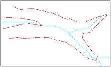
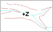
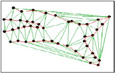
Example

The contours The triangulation - We can see several flat triangles here
4032001TIN02.jpg (8917 bytes) 4032001TIN03.jpg (18667 bytes)
The elevation The slope- The green areas indicate
Slope = 0 (flat triangles)
4032001TIN04.jpg (10879 bytes) 4032001TIN05.jpg (9819 bytes)

How can we avoid the flat triangles ?
  • By adding more mass points
  • Generalizing the contours
  • By adding break lines

Break lines

Linear features which define and control surface behavior in terms of smoothness and continuity are called break lines.

Types break lines:

  • Soft break lines are used to ensure that linear features and polygon edges are maintained in the tin surface model by enforcing the break line as tin edges. However, they do not define interruptions in surface smoothness – break lines with no Z value
  • Hard break lines define interruptions in surface smoothness – break lines with  Z value

Example:

  No break lines Soft break lines Hard break lines
The Data 4032001TIN06.jpg (6322 bytes) 4032001TIN09.jpg (6454 bytes) 4032001TIN12.jpg (6854 bytes)
The Triangulation 4032001TIN07.jpg (12367 bytes) 4032001TIN10.jpg (13514 bytes) 4032001TIN13.jpg (12275 bytes)
The Surface 4032001TIN08.jpg (6718 bytes) 4032001TIN11.jpg (6964 bytes) 4032001TIN14.jpg (7826 bytes)
3D View 4032001TIN15.jpg (9329 bytes) 4032001TIN16.jpg (9399 bytes) 4032001TIN17.jpg (10918 bytes)
 

Storing TINs

There are basically two ways of storing triangulated networks:

  • Triangle by triangle
  • Points and their neighbors

The first method is better for storing attributes (slope, aspect ..) for each triangle, but uses more storage space. The second one is better for generating contours and uses less storage space, but slope, aspect , etc. must be calculated and stored separately.

TIN and ET Surface

ET Surface 4.0 and above can store TINs using both data structures above.

For any comments and enquiries contact: webmaster@ian-ko.com
Esri and all Esri products mentioned are trademarks of Environmental Systems Research Institute, Inc.
Copyright: Ianko Tchoukanski