
Topology problems when editing in ArcMap
Problems linked to the coordinate precision
Any GIS software needs to use some rounding when representing real world coordinates. The term Coordinate Precision refers to the mathematical exactness of a coordinate and is based on the possible number of significant digits that can be stored for each coordinate.
GIS software normally stores coordinates in one of three formats: long integer, single or double precision real numbers. A long integer can store up to 9 significant digits, a single precision real up to 7 and a double precision real up to 13 significant digits. So no matter what format is used for storing the spatial data some rounding occurs when storing coordinates.
We will not discuss here the precision used in ArcGIS. The purpose of this page is to highlight the problems that might occur during some editing task linked in most cases to the coordinate precision.
Lets assume that long integers are used for storing numbers. Depending on the rounding formula the numbers will be stored similarly to the examples below:
123456.7891 will be stored as 123456.789
123456.7899 will be stored as 123456.789
Therefore all the possible coordinates can be represented as a very fine grid. If a point is derived from a spatial operation and the coordinates calculated somewhere in between the grid points, the point is moved slightly and snapped to the grid.
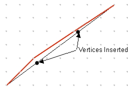
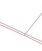
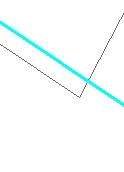
The original (black) line in the image is described by its From and Two points. All the points from the line can be derived using the equation
y = Ax + B
Once calculated however the coordinates must be rounded in order to be stored as long integers and therefore are snapped to the coordinate grid. As a result we do not have a straight line anymore, but a polyline (red) with three straight segments each having its own equation.
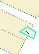
Example:Inserting new vertices in an existing polygon
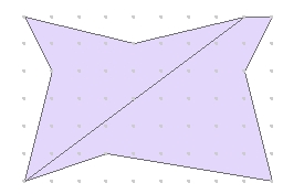
Unlike in the coverage data structure each polygon stored in Shapefiles or in Geodatabases has its own boundary. If we have two adjacent polygons their common boundary is stored twice (separately for each polygon).
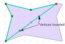
If we insert vertices in one of the polygons, the new coordinates will be calculated, rounded and snapped to the coordinate grid, then stored in the dataset.
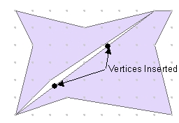
As a result the common boundary of the two polygons will not be common anymore. Extremely small gaps and/or overlaps will be introduced in the dataset. These topological problems initially are so small that cannot be seen even if zoomed with the maximum allowed zoom factor in ArcMap (which is quite limited), but they exist and the more editing is performed the larger they get.
If you have ArcGIS Standard or Advanced license the problems can be rectified by building topology and validating it, but there is little that the ArcGIS Basic users can do about these problems.
Below are some example of how ArcMap tools that might produce incorrect topology
Modify Feature ==> Insert vertex to a polygon (See the example above)
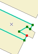
Cut Polygon Features
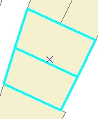
Two polygons to be cut are selected
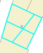
After the standard ArcMap Cut Polygon features task
There is no vertex introduced in the neighboring polygon that was not cut.
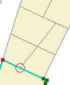
When zoomed to the indicated location - Overlaps are introduced by the task performed
Standard Clip Tool
The larger polygon to be clipped with the highlighted one
New vertices are introduced in the clipped polygon
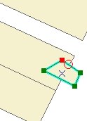
No new vertices are inserted in the clip polygon.
Zooming to the indicated location shows that overlap has been created